Configuring a Site-to-Site VPN
Network Security, Router Configuration, Access Management, Encryption, Data Integrity, VPN Protocols, Troubleshooting
Contents
Scenario
In this Packet Tracer lab, I will be configuring a site-to-site VPN. A site-to-site VPN (Virtual Private Network) connects entire networks to each other over the Internet, allowing them to function as a single, unified network. This type of VPN is commonly used to connect branch offices to a main office, providing a secure communication channel for data exchange.
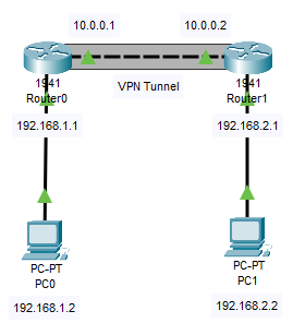
This is the network topology I will be using:
Objectives
- Confirm connectivity between routers
- Configure RIP on both routers
- Configure phase 1 of the IKE tunnel
- Configure phase 2 of the IKE tunnel
- Define access control lists
- Configure a crypto map (apply it to interfaces)
- Ping PC1 from PC0
Results
📄 Task 1: Confirm connectivity between routers
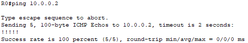
The VPN tunnel will consist of the 10.0.0.0/8 network. The interfaces connecting the two routers will have the IP addresses 10.0.0.1 and 10.0.0.2. To confirm connectivity, I will ping across the 10.0.0.0 link.
📄 Task 2: Configure RIP on both routers
I will use the following commands to configure the Routing Information Protocol (RIP) on both routers:
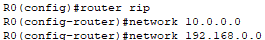
The router rip command is used to enable RIP on the router. RIP is a distance-vector routing protocol used in local and wide area networks. RIP will enable the routers to exchange routing information dynamically.
I also configure the networks that will use RIP (10.0.0.0/8, 192.168.1.0/24, 192.168.2.0/24).
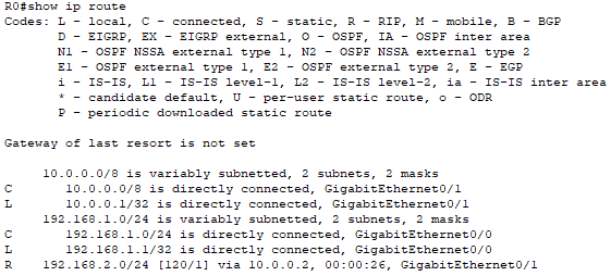
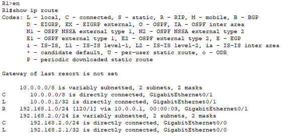
Next, I show each router’s routing table to ensure that all routes are visible.
Router0:
Router1:
📄 Task 3: Configure phase 1 of the IKE tunnel
Internet Key Exchange (IKE) is a protocol used to set up a secure and encrypted communication channel between two devices (usually routers) in a VPN. It works in two phases:
- Phase 1: Negotiate the IKE SAs and establish a secure and authenticated channel.
- Phase 2: Negotiate the IPSec SAs that will be used to protect the actual data traffic.
First, I will configure phase 1 of the IKE tunnel. This will define how IKE authenticates IPsec peers (or the devices authenticating traffic through the VPN tunnel. In this case, the two routers) and negotiations of IKE SAs (Security Associations). A Security Association is a set of parameters and keys that define secure communication between two network devices.
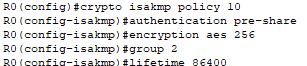
Notice ISAKMP in the first line which stands for Internet Security Association and Key Management Protocol. It is a protocol used to establish, negotiate, modify, and delete SAs and cryptographic keys in a network. The SA will consist of the following:
-
Pre-shared keys will be used for authentication. A pre-shared key is a secret key that both routers must know and use to authenticate each other.
-
AES (Advanced Encryption Standard) with a key length of 256 bits will be used to encrypt the IKE messages exchanged between the peers (routers) during this negotiation phase.
-
When symmetric keys are generated and exchanged, the routers will use Diffie-Hellman group 2 key exchange protocol, which uses a 1024-bit key.
-
The lifetime of the IKE SA will be set to 86400 seconds, or 24 hours. After this time, the IKE SA will expire and need to be renegotiated. Regularly renegotiating the SA helps maintain security by periodically refreshing the encryption keys.
📄 Task 4: Configure phase 2 of the IKE tunnel
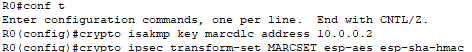
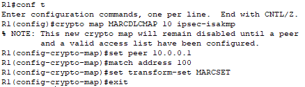
In the first command on Router0, I set the pre-shared key (marcdlc) used by both routers to authenticate each other. Next, I set the IPsec peer as the other router at the other end of the VPN tunnel (10.0.0.2).
Next, I configure the transform set used to encrypt the data payload and the algorithm for ensuring data integrity. The transform set will be called “MARCDLCSET.” ESP (Encapsulating Security Payload) is one of the two main IPSec protocols (the other being AH, Authentication Header) used to provide data confidentiality, integrity, and authenticity in IPSec VPNs. To encrypt the payload, AES will be used. To ensure data integrity, SHA (Secure Hash Algorithm) with HMAC (Keyed-Hash Message Authentication Code) is used here.
I repeat these same steps on Router1.
📄 Task 5: Define access control lists
In this step, I will define an Access Control List (ACL) that specifies the traffic to be encrypted and sent through the IPSec VPN tunnel. I do this on both routers.

The above command for Router0 states that all LAN-to-LAN traffic from the 192.168.1.0/24 network to the 192.168.2.0/24 network will be permitted through the VPN tunnel.
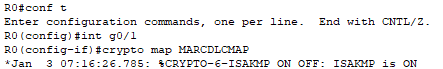
📄 Task 6: Configure a crypto map
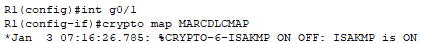
Next, I will configure a crypto map on the G0/1 interface of Router0, which is the interface linking it to Router1:
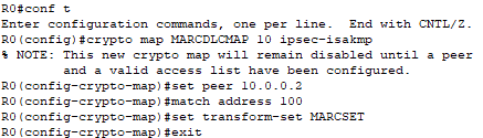
I am configuring a crypto map named “MARCDLCMAP” to define how the VPN will be set up and secured. The crypto map specifies the:
- Peer IP Address: The remote endpoint of the VPN tunnel.
- Access Control List: The traffic that should be encrypted and sent through the tunnel.
- Transform Set: The security protocols and algorithms (ESP with AES and SHA-HMAC) to use for protecting the traffic. This was established in Task 5.
Finally, I apply the map to G0/1.
I repeat these steps on Router1.
📄 Task 7: Ping PC1 from PC0
To confirm that the VPN tunnel is configured correctly, I will turn on ISAKMP debugging on Router0 and attempt to ping PC1 from PC0. The ICMP packets that travel through the VPN tunnel will be logged by Router0.
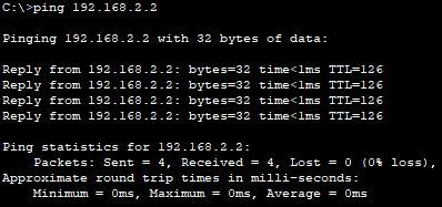
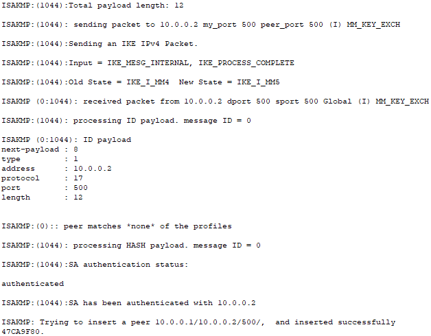
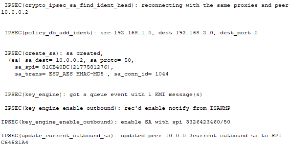
From the debugging logs, I can see that the Router0 has been fully authenticated with Router1. I can also see that a Security Association between the two routers has been successfully created with all of the necessary security parameters to encrypt the data payload and ensure data integrity.